Measuring Floppy Drive rotation speed - Part 3
This is a continuation of Measuring Floppy Drive rotation speed and Measuring Floppy Drive rotation speed - Part 2. Just a small summary, where we are:
In Part 1, we used the sample BASIC program, which contained a small assembler code to read the index signal from the floppy disk controller. This gave the result of about 390 rpm. This value is probably wrong, as it exceeds the specification way too much and the drive still works. At least, it can still read the old diskettes. The expected rotation speed for a DD (double density) 5 1/4” floppy drive is 300 rpm.
In Part 2, I made sure, that the assembly routine wouldn’t be interrupted by any other code by disabling the interrupts. That way, the measurement should be as accurate as possible. But it still resulted in 388 rpm. I’m missing something here.
There are still at least two different ways to measure the drive rotation speed: Using a stroboscope pattern and measuring the index signal directly on the floppy bus with an oscilloscope.
This article is about Stroboscope patterns.
These old floppy drives have still a stroboscope pattern on the spindle. Before the LED light, there often was fluorescent lamps (tubelights) used. These lamps flickered at the same frequency as the mains. In Europe with 50Hz, in the USA with 60Hz.
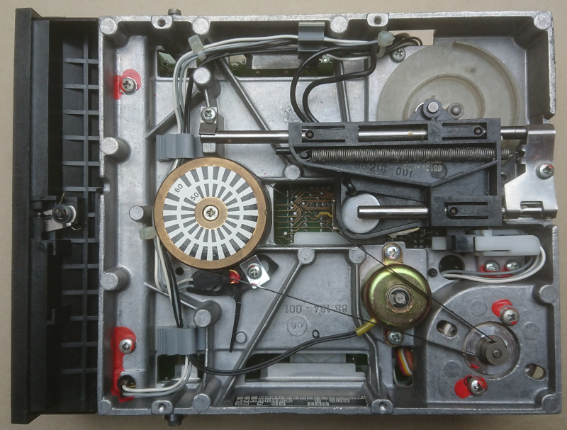
The pattern on the drive in combination with the flickering light made it possible to adjust the drive speed: The goal was, that the pattern stand still. If the pattern was moving, then the drive was either too slow or too fast. There is usually a potentiometer to adjust the spindle motor speed.
On the image you can see, that there are actually two patterns: The inner pattern for 50Hz and the outer pattern for 60Hz.
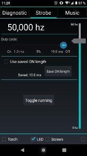
Since we have today LED lights, which don’t flicker (at least not with 50Hz), you need another source of stroboscope lighting: There are various smartphone apps, which do the job. I have chosen the app Strobily. This app uses the camera’s flash light and switches it on and off with a given frequency. Originally this app is for adjusting the speed of a turntable but can be used to check the speed of your floppy drive as well.
So here is a video with a 50 Hz stroboscope light:
As you can see, the inner ring is slowly moving. That means, the drive speed is not exactly 300 rpm. It seems to be slowly moving forward, but that could also be a illusion. From that method, one can only say, whether the speed is correct or not. Maybe, whether the speed is vastly out of specification or almost ok. In that case, the speed seems to be almost ok (only slow moving pattern), but not perfect. If the speed would be perfect the pattern would stand still.
Just for completeness, the same drive, but with a 60 Hz stroboscope light:
The same result: the outer pattern is slowly moving, which means the drive speed is not perfectly in spec, but also not completely out of scope.
Note, that these videos where taken, when the drive was outside the computer. Which means, the drive has been powered with a different power supply, which might change the result. But this measurement anyway doesn’t provide an exact value, if the drive speed is not perfectly. The method can only be used to adjust the drive’s speed when maintaining the drive.
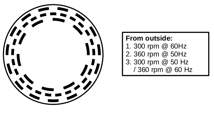
Newer drives don’t have these patterns anymore. But you can create it yourself. I’ve drawn such a pattern using LibreOffice Draw and some macro code. Here’s the result:
You can download it as strobosokop-pattern-floppy-drive.pdf (PDF) or as strobosokop-pattern-floppy-drive.odg (ODG).
The macro code looks like this... (click to expand)
REM  *****  BASIC  *****

Sub Main
  Dim oDocument As Object
  Dim oPage As Object

  oDocument = ThisComponent
  oPage = oDocument.getDrawPages().getByIndex(0)

  diameter = 85
  oPage.add(CreateCircle(oDocument, oPage.BorderLeft - 250, oPage.BorderTop - 250, diameter*100 + 500, 0))

  ' pattern for 300 rpm @ 60 Hz: 30 x 12°
  DrawPattern(oDocument, oPage, diameter, 85, 12, 30)

  ' pattern for 360 rpm @ 50 Hz: 50 x 7.2°
  DrawPattern(oDocument, oPage, diameter, 75, 7.2, 50)

  ' pattern for: 300 rpm @ 50 Hz / 360 rpm @ 60 Hz: 20 x 18°
  DrawPattern(oDocument, oPage, diameter, 65, 18, 20)
End Sub

Sub DrawPattern(oDocument, oPage, diameter, patternSize, angleStep, steps)
  Dim left
  Dim top

  patternWidth = 250
  borderLeft = oPage.BorderLeft
  borderTop = oPage.BorderTop
  angle = 0
  left = borderLeft + (diameter - patternSize) * 100 / 2
  top = borderTop + (diameter - patternSize) * 100 / 2
  For i = 0 To steps
    If i Mod 2 = 0 Then
      oPage.add(CreateSector(oDocument, left, top, patternSize * 100, angle, angle + angleStep))
    End If
    angle = angle + angleStep
  Next i
  'oPage.add(CreateCircle(oDocument, left, top, patternSize, 0))
  oPage.add(CreateCircle(oDocument, left + patternWidth, top + patternWidth, patternSize * 100 - patternWidth * 2, 16777215))
End Sub


' x, y, diameter in 1/100 mm
Function CreateSector(oDocument, x, y, diameter, startAngle, endAngle)
  Dim shape As Object
  Dim point As New com.sun.star.awt.Point
  Dim size as New com.sun.star.awt.Size

  shape = oDocument.createInstance("com.sun.star.drawing.EllipseShape")
  shape.LineWidth = 100 ' 1mm
  shape.LineColor = 0 ' black

  shape.CircleKind = com.sun.star.drawing.CircleKind.SECTION
  shape.CircleStartAngle = 100 * startAngle
  shape.CircleEndAngle = 100 * endAngle

  shape.FillColor = 0 ' black

  point.X = x
  point.Y = y
  shape.setPosition(point)

  size.Width = diameter
  size.Height = diameter
  shape.setSize(size)

  CreateSector = shape
End Function

' x, y, diameter in 1/100 mm
Function CreateCircle(oDocument, x, y, diameter, color)
  Dim shape As Object
  Dim point As New com.sun.star.awt.Point
  Dim size as New com.sun.star.awt.Size

  shape = oDocument.createInstance("com.sun.star.drawing.EllipseShape")
  shape.LineWidth = 100 ' 1mm
  shape.LineColor = color ' 16777215 ' white

  shape.CircleKind = com.sun.star.drawing.CircleKind.FULL

  shape.FillColor = 16777215 ' white

  point.X = x
  point.Y = y
  shape.setPosition(point)

  size.Width = diameter
  size.Height = diameter
  shape.setSize(size)

  CreateCircle = shape
End Function
It draws some circles and sectors. For the innermost pattern (300 rpm at 50Hz), I used 20 sectors each using 18° of the full circle. Every second sector is black, that’s the pattern. 300 rpm means there are 5 rotations per second (5 Hz) and one rotation needs 200ms. Between two strobe light flashes with 50Hz exactly 20ms pass by. If we divide the full circle into 10 sectors, then with every strobe light flash, the disc would rotate by exactly one sector and after 10 flashes, the disc has done a full rotation. In order to see the different sectors, I painted half of the sectors black, the other half white so that a black-white-pattern is visible. Essentially I painted 20 sectors and every second sector is black which creates exactly this pattern.
Here’s a video of this pattern in action. Note that I used this on a newer HD drive, which rotates with 360 rpm. So the middle pattern should stay still at 50Hz.
Conclusion: The alphatronic floppy drive might not rotate at exactly 300rpm, but it doesn’t appear to be too bad.
To be continued with measuring the index pulse from the drive directly with an oscilloscope.
Comments
No comments yet.Leave a comment
Your email address will not be published. Required fields are marked *. All comments are held for moderation to avoid spam and abuse.