Using the serial port - part 1.5 - bitbanging
Introduction
As we figured out in the last post about the serial port of the Alphatronic P2, using the serial port didn’t work. It got stuck. I tried to send data, but the send buffer didn’t seem to be emptied.
Looking at the schematics and the board, I could identify some solder bridges: There is a configuration
possibility to use different clocks. If the default configuration would have been used, the program should
have worked: Sending data at 4800 baud, using the internal clock with a factor of 16x. So, the internal
clock would be 4800x16 = 76800 Hz. But apparently it isn’t?
Clock
One theory I have is: The solder bridges look tampered. So, maybe the external clock is used? This is an actual alternative configuration. The socket has some signal lines for TxC and RxC - so you could even use different clocks for transmitting or receiving.
It shouldn’t be that hard to drive these clock lines, should it? These are external lines and in the schematic I can see, that there is a line driver, that converts from the physical rs232 signal levels to TTL (5V) levels for the 8251A chip. So, we need to generate somehow a clock.
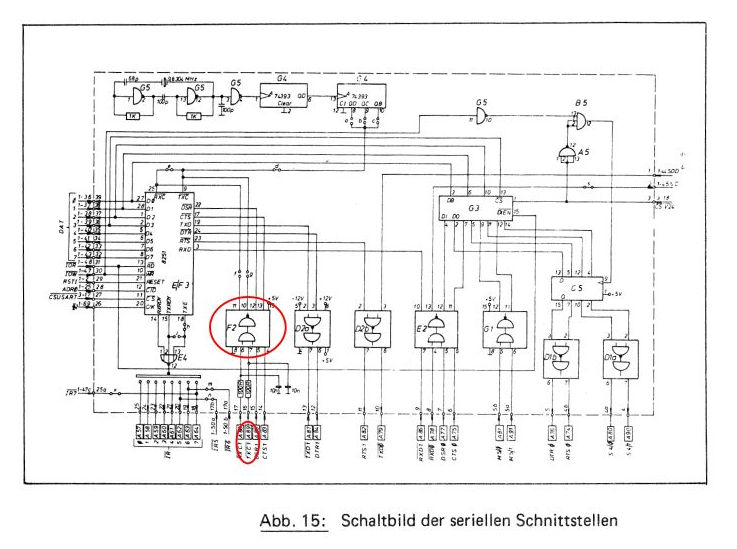
You can see, that the external TxC line at the bottom is connected to a chip numbered “F2”. This is actually a 75154 Quad Differential Line Receiver. Input is +/-25V max and output is TTL. The output is connected to the 8251.
The idea is, to use one of the signal lines, e.g. RTS, and a standard USB-to-RS232-adapter and toggle this line. This is like bitbanging the clock. This blog post is about generating this clock signal - hence it is part 1.5. Using it will be part 2.
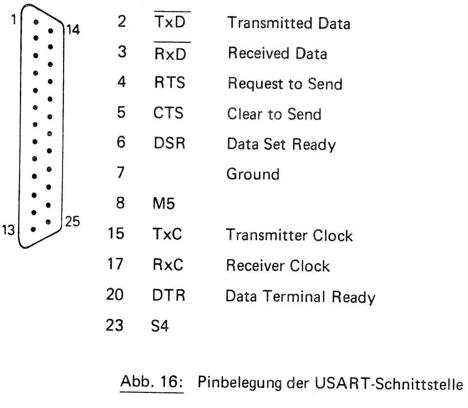
The idea is then, to connect the RTS signal line to the TxC line with jumper wire. All signals are available in the 25 pin serial port of the Alphatronic:
Java? Why not?
I could of course use a microcontroller to generate clock or even just a quartz or timer chip (555). But then I would also need a level converter (such as MAX232), so that I can interface it directly.
So, I simply use a USB-to-RS232-adapter instead, which contains all the electronics already. Then I could use a terminal program and toggle the RTS line manually. But that would be difficult, to click that fast and in that constant time. My goal would be, to also use the RS232 adapter to receive at 4800 baud, what the Alphatronic was sending. So, the clock must be fairly accurate.
I’m using Java, because I know it is possible to interface serial adapters - the Arduino IDE contains a serial monitor. And I want to program it myself.
One library, that looks good is jSerialComm. It is platform independent, that means it potentially runs under Windows and MacOS as well. But also under Linux. And it has an API to toggle RTS, CTS, DTR and DTS manually.
I’m using maven, so you can simply add this library as a dependency:
        <dependency>
            <groupId>com.fazecast</groupId>
            <artifactId>jSerialComm</artifactId>
            <version>2.9.2</version>
        </dependency>
And then we can create a simple main program:
public class JavaSerialClock {
    public static void main(String[] args) throws InterruptedException {
        SerialPort commPort = SerialPort.getCommPort("/dev/ttyUSB0");
        System.out.println("commPort = " + commPort + " (" + commPort.getSystemPortPath() + ")");
        // ...
    }
}
First, I’m opening /dev/ttyUSB0 - that’s where my USB serial adapter appears. There is also the static
method SerialPort.getCommPorts() which returns an array of all detected serial ports. That will be handy
if you create a GUI and want to provide the available ports as options. But I’m using here just my one
single port. This will be a program for just one specific task - generating the clock.
Next part is initializing the serial port: 8n1@4800 baud, no hardware flow control.
        // 8n1@4800
        int baudrate = 4800;
        commPort.setBaudRate(baudrate);
        commPort.setParity(SerialPort.NO_PARITY);
        commPort.setNumDataBits(8);
        commPort.setNumStopBits(SerialPort.ONE_STOP_BIT);
        commPort.setFlowControl(SerialPort.FLOW_CONTROL_DISABLED);
        commPort.setComPortTimeouts(SerialPort.TIMEOUT_READ_BLOCKING, (int) TimeUnit.SECONDS.toMillis(30), 0);
        commPort.clearDTR();
        commPort.openPort();
I plan to use commPort.setDTR() and commPort.clearDTR() and just toggle it. I want to use the same
clock factor of 16x, so that I basically don’t need to adjust the BASIC program. Of course, I shouldn’t wait for the
DSR signal, since that won’t be connected. So, a little change is needed, but not for the baudrate/timing.
That means I need to create a frequency of 4800x16=76800 Hz. It should have as usual a 50% duty cycle, that
means I need to switch on the DTR signal half of the period and switch it of again. One period takes 1/76800 s
which is 13µs or 13020ns. And half period is therefore 6510ns.
        double frequency = baudrate * 16;
        int halfPeriodNanos = (int) (0.5 * 1.0 / frequency * TimeUnit.SECONDS.toNanos(1));
        System.out.println("halfPeriodNanos = " + halfPeriodNanos);
Uh… that’s pretty short. It’s definitely less
than one millisecond, so Thread.sleep() won’t work. There is another overload which takes milliseconds and nanoseconds
and you can provide 0ms and just provide nanoseconds. But I tried it - the timing is not very accurate.
Stackoverflow knows the solution: How to suspend a java thread for a small period of time, like 100 nanoseconds?.
The solution is - busy waiting. Repeatedly check the nano seconds with System.nanoTime() until the right
amount has passed.
I need a function now, that implements the busy waiting for a given amount of nano seconds:
    private static void busyWait(long nanos) {
        long start = System.nanoTime();
        long end = 0;
        while (end - start < nanos) {
            end = System.nanoTime();
        }
    }
Ok, now I can define a runnable, that drives the clock:
        Runnable clock = () -> {
            long start = System.currentTimeMillis();
            System.out.println("Toggling DTR...");
            while (System.currentTimeMillis() - start < TimeUnit.SECONDS.toMillis(100)) {
                commPort.setDTR();
                busyWait(halfPeriodNanos);
                commPort.clearDTR();
                busyWait(halfPeriodNanos);
            }
            System.out.println("Done");
        };
It will run 100s and toggle the DTR line suitable as the clock for the given baudrate.
Let’s start this runnable in a new thread:
        Thread clockThread = new Thread(clock);
        clockThread.start();
Arguably, that could have been done without a thread, but we’ll need it later. Because eventually we want to receive in parallel some data from the serial port, while we are driving the clock.
Next step is to try to receive something:
        byte[] buffer = new byte[10];
        int readBytes = commPort.readBytes(buffer, buffer.length);

        System.out.println("readBytes = " + readBytes);
        String hexString = IntStream.range(0, buffer.length).map(i -> buffer[i] & 0xff)
                .boxed()
                .map(Integer::toHexString)
                .map(s -> "0x" + s)
                .collect(Collectors.joining(", "));
        System.out.println("hexString = " + hexString);
        System.out.println("buffer = \"" + new String(buffer, StandardCharsets.ISO_8859_1) + "\"");

        commPort.closePort();
The call to commPort.readBytes() will block until timeout. We configured a 30s timeout when
initializing the port (TIMEOUT_READ_BLOCKING). There is also semi-blocking, which blocks until the
first byte is received, but we block until all 10 bytes have been received - or the timeout occurred.
We then convert the bytes into some output, that we can easily recognize. The number of received
bytes are printed as well (readBytes) and might be 0.
That’s the whole program for now. Let’s try to verify it with a frequency meter. We need to connect signal ground and DTR signal lines, which is pin 5 (GND) and pin 4 (DTR). See Wikipedia - Serial ports: Pinouts.
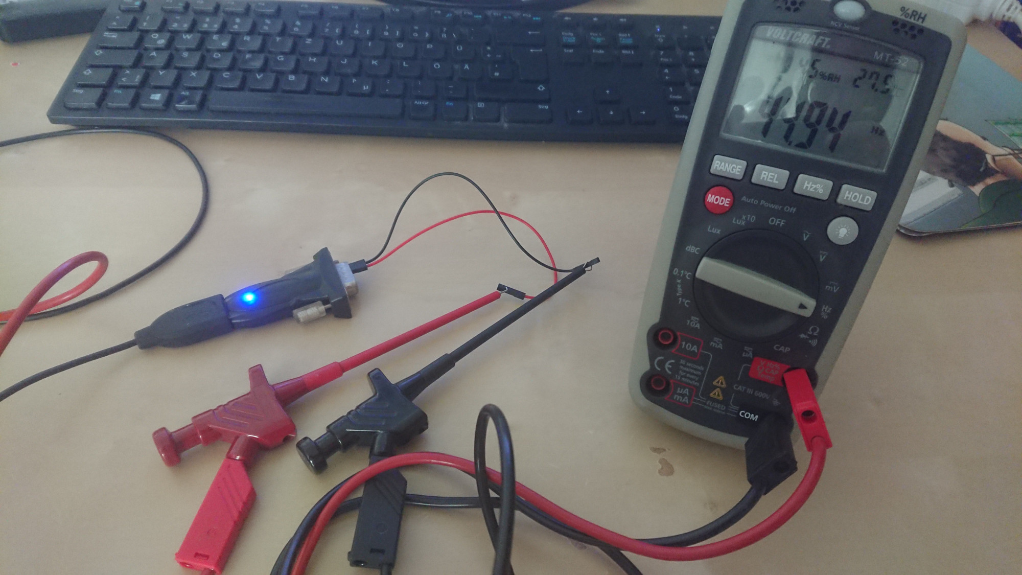
Ok, the first try is not so promising. There is some toggling, but the frequency meter jumps largely, e.g. between 5kHz and maybe 60kHz? Not very stable, that clock is probably not a very good quality.
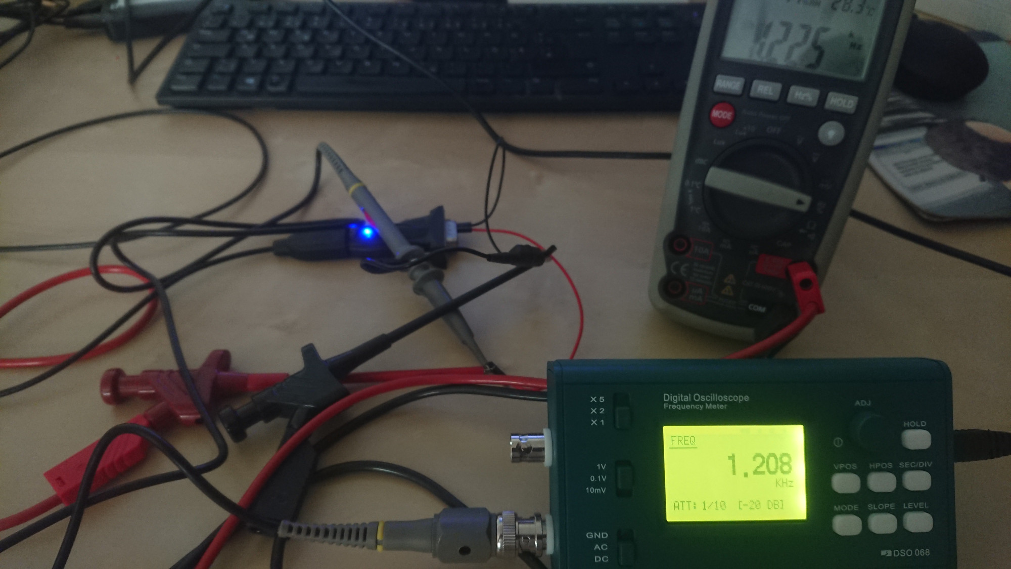
Let’s use the DSO:
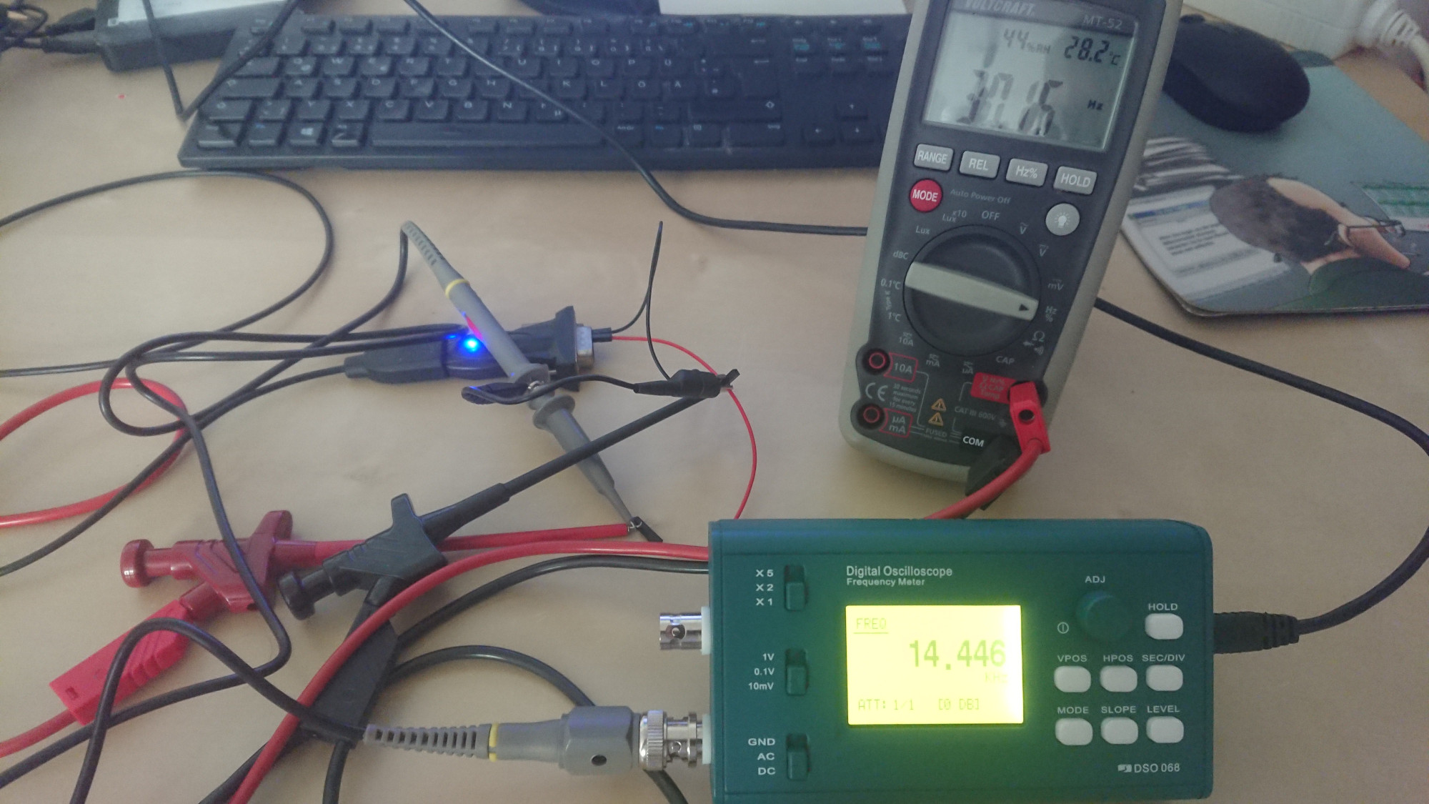
So, it’s definitely not the 76800 Hz that we need. We probably can’t be that fast. It actually shouldn’t be important, what frequency exactly we have for the transmitter. I would be happy to just see, that the transmitter is not stuck anymore with a full buffer and can send the bytes out. Of course, the receiver won’t be able to receive the bytes, because it will use a different clock.
Maybe we can use 75 baud, then we would need only 1200 Hz as the clock.
It seems, we have some overhead - the frequency is around 1kHz. So, we are too slow. We need to wait a bit shorter.
We can do that by pretending we started to wait a bit earlier by reducing start by some amount. After a bit of
trying and tweaking, busyWait looks like this:
    private static void busyWait(long nanos) {
        long start = System.nanoTime();
        start -= 0.2*nanos; // remove overhead
        long end = 0;
        while (end - start < nanos) {
            end = System.nanoTime();
        }
    }
We come close to 1200 Hz. Let’s hope, that this is accurate enough. We can then set our receiver side to 75 baud and should be able to get some bytes.
–> int baudrate = 75;
Verification
I want to verify that this bit banging works in principle. My idea is now to not drive a clock, but drive actual bits on the RxD line. If I connect the DTR signal directly to the RxD pin at the same adapter, I should be able to toggle that pin and be able to receive something. If I do the toggling correctly.
When sending data, we need to send bit by bit and also send a start bit and a stop bit. When no data is sent, the TxD signal (which we are simulating/generating) is kept in mark level (logical 1, below -3V). The physical and logical levels of TxD and DTR are inverted, that means we need to set DTR to logical 0 to have a physical signal below -3V and thus a logical 1 for TxD.
We initialized the DTR signal at the beginning with commPort.clearDTR();, so that’s fine.
The first bit will be the start bit. We need to assert DTR for one bit’s time. One bit at 75 baud takes 1/75 seconds = 13.33ms. Directly after the start bit, the first bit will be transmitted. If it is a 0, then we keep DTR asserted, if it is a 1, we need to clear DTR.
When we send one byte - which is one word in out 8n1 setting - the least significant bit is transmitted first. After we sent 8 bits, we need to send one stop bit. This is a mark, that means we need to deassert DTR.
Then we would be immediately ready to start transmitting the next word. The stop bit is enough gap in theory. But I clearly want to separate the words, that why I’m waiting between each word 500ms.
Now the pieces in code, one by one:
        Runnable sender = () -> {
            int bitLengthNanos = (int) (1.0 / baudrate * TimeUnit.SECONDS.toNanos(1));
            commPort.clearDTR(); // no data
            busyWait(TimeUnit.MILLISECONDS.toNanos(500));
            System.out.println("Sending...");
            sendString(commPort, "**01234567", bitLengthNanos);
            System.out.println("Done");
        };

        // Thread clockThread = new Thread(clock);
        // clockThread.start();
        Thread senderThread = new Thread(sender);
        senderThread.start();
This defines a new sender thread and starts it. Note: the clockThread is commented out, as that would toggle the same DTR line.
Next we need the helper method sendString:
    private static void sendString(SerialPort commPort, String s, long bitLengthNanos) {
        for (int i = 0; i < s.length(); i++) {
            sendByte(commPort, s.charAt(i), bitLengthNanos);
        }
    }
This just sends byte by byte.
    private static void sendByte(SerialPort commPort, int c, long bitLengthNanos) {
        //System.out.println("c = 0x" + Integer.toHexString(c));
        // Send start bit
        sendBit(commPort, false, bitLengthNanos);
        for (int i = 0; i < 8; i++) {
            int mask = 1 << i;
            sendBit(commPort, (c & mask) == mask, bitLengthNanos);
        }
        // Send stop bit
        sendBit(commPort, true, bitLengthNanos); // stop bit

        // Idle
        commPort.clearDTR(); // no data
        busyWait(TimeUnit.MILLISECONDS.toNanos(500));
    }
The method sendByte now sends single bit and creates the framing with start and stop bits.
There we also have our 500ms idle gap between the words.
    private static void sendBit(SerialPort commPort, boolean bit, long bitLengthNanos) {
        if (!bit) {
            commPort.setDTR();
        } else {
            commPort.clearDTR();
        }
        busyWait(bitLengthNanos);
    }
The method sendBit now just sets the DTR line according to the bit value and waits for
one bit’s time to pass. It uses the same busyWait method we already have.
We still have our receiving logic present, that means we start the sender thread (which actually waits 500ms before sending the first bit) and then we immediately start receiving using the library, which uses the real hardware to interpret our bit banging. If all goes well, we should see the string “**01234567” or at least part of it in the received 10 bytes.
One thing: wiring. We don’t need to connect the signal ground, but we need a wire loop between DTR and RxD pins. DTR is pin 4 and RxD is pin 2.
Ok, so far the theory. It is extremely difficult to have that precise timing, that the sender actually works. I experimented a bit - the busywait removes some overhead. With 75 baud, that means 75Hz (and not the 16x clock) the removed overhead is too much. But I couldn’t find a better value. I guess, the variations are too big. We would need to wait exactly 13.3ms. In my experiments, it worked a bit better when switching to 1200 baud and keeping the overhead removal. But it is not reliably repeatable. I’ve sawn my string being received one or two times, but never in a row. You can see that there is some jitter, when some characters are received correctly, but the others are not.
Summary
So that was an interesting experiment, whether we can you Java for that. And the result is: yes, you can. But
the clock is very, very low quality. The reason is, you can’t really control the timing in your Java application.
It all depends, which other programs are running, when your threads are scheduled to execute. And according
to the SO question: Accurate timing the
method System.nanoTime() doesn’t necessarily return nano seconds precision. That’s also documented in the javadoc
of the method - the only guarantee is, that it is at least milliseconds precision. So I guess, the biggest
problem is the busywait method.
I guess, I need to generate the clock in a different way. Probably using a Arduino or so and just toggling a GPIO pin. But I also need a MAX232 or similar for the correct voltage levels.
The whole program can be downloaded here: JavaSerialClock.zip or on github: adangel/alphatronic-code.
Comments
No comments yet.Leave a comment
Your email address will not be published. Required fields are marked *. All comments are held for moderation to avoid spam and abuse.