Measuring Floppy Drive rotation speed - Part 2
This is the continuation of Measuring Floppy Drive rotation speed. We need a better machine program to measure the exact duration between two index hole detections. The plan is, that we first wait, until the index is detection, then start to count until the index is detected again.
Just to verify, we should have a short look at the floppy controller spec. With “IN 54H”, we read the status register. The floppy controller in the Alphatronic is “SAB 1791 02-C”. A search on datasheetarchive reveals this as “Floppy-Disk-Controller, SS” and “40-DIC/DIP” casing. After a search for the terms “floppy-disk-controller” it turns out, that this chip has been produced by Siemens - and there is the actual data sheet. It says “Compatible with Industry Standard 179X”, so you could also use any other datasheet for the 179X family of floppy disk controllers.
The status register has 8 bits. The second bit (bit “S1”) is the index bit and described as “When set, indicates index mark detected from drive. This bit is an inverted copy of the #IP input”. We use a bit mask of “0x40” to check whether the index bit is set or not (via ANA B - A = A & B). Since the status register has this layout:
                      (Bits)
+-----+-----+-----+-----+-----+-----+-----+-----+
|  7  |  6  |  5  |  4  |  3  |  2  |  1  |  0  |
+-----+-----+-----+-----+-----+-----+-----+-----+
| S7  | S6  | S5  | S4  | S3  | S2  | S1  | S0  |
+-----+-----+-----+-----+-----+-----+-----+-----+
I would now have expected, that we need the bitmask “0x02”… In the datasheet, there is mentioned the feature “inverted data bus”. The data of the status register read is transmitted through the data bus. If it is inverted, then yes, it’s actually bit 6 we are interested and that is bitmask “0x40”.
Ok, so far so good. Let’s just try it. I’ll start at a different origin for ease of counting.
                                       ORG     FF00H
                                       PUBLIC  READ_INDEX_DURATION
FF00'  3E D4      READ_INDEX_DURATION: MVI     A,D4H    ;FORCE-INTERRUPT command with IP (index pulse)
FF02'  D3 50                           OUT     50H      ;execute command
FF04'  06 40                           MVI     B,40H    ;Mask for index detected flag in status register
FF06'  11 0000                         LXI     D,0      ;init counter in D
FF09'  DB 50                           IN      50H      ;reading the command register?? apparently clearing the IRQ flag
FF0B'  DB 54                   LOOP1:  IN      54H      ;reading status register into A
FF0D'  A0                              ANA     B        ;check if index is set
FF0E'  CA 0BFF'                        JZ      LOOP1    ;if no index yet, busy wait...
FF11'  DB 50                           IN      50H      ;clearing the INDEX flag for next index detection
FF13'  13                      LOOP2:  INX     D        ;counting now...
FF14'  DB 54                           IN      54H      ;reading status register into A
FF16'  A0                              ANA     B        ;check if index is set
FF17'  CA 13FF'                        JZ      LOOP2    ;jump back, if no index and keep counting
FF1A'  73                              MOV     M,E      ;copy counter (low Byte) to memory at [H]
FF1B'  23                              INX     H        ;
FF1C'  72                              MOV     M,D      ;copy counter (high Byte) to memory at [H]
FF1D'  C9                              RET
That should give us the counter of exactly one disk rotation - that is LOOP2. We need 5 (INX) + 10 (IN) + 4 (ANA) + 10 (JZ) = 29 CPU cycles. We have a 16 bit counter in register D. Will it overflow? Let’s assume the rotation speed is at the standard 300 rpm, that means one rotation takes 0.2 seconds. At 3 MHz, these are 600,000 CPU cycles. Divided by 29 we get 20,690 which is smaller than 64k - good. No problem here.
Now the BASIC program. I keep it a bit simpler, no fancy graphics output of the histogram. But it’s faster to type in, because it’s shorter.
100 '************** DRIVEROT
110 CLEAR , &HFF00
120 DEFINT D
130 GOSUB 500
140 PRINT"In the last used drive a floppy has to be inserted!"
150 INPUT"How many measurements should be taken"; COUNT
160 DIM DAT%(COUNT)
170 FOR D=0 TO COUNT-1
175     PRINT"  Start measurement ";D
180     CALL RID(LOOPS%)
190     DAT%(D)=LOOPS%
195     PRINT"    result:";D;"->";DAT%(D)
200 NEXT
210 PRINT"Data ready"
220 MIN=DAT(0) :MAX=MIN :SUM=0
230 FOR D=0 TO COUNT-1
240     IF DAT(D)<MIN THEN MIN=DAT(D)
250     IF DAT(D)>MAX THEN MAX=DAT(D)
260     SUM=SUM+DAT(D)
270 NEXT
280 MEAN=SUM/COUNT
290 LPS=103448! 'loops per second: 3 MHz/29 cycles - dur. of one loop
300 RPM=INT(60*LPS/MEAN+.5)
310 DIF=MAX-MIN
320 PRINT"  Minimum:";MIN/LPS;"s"
330 PRINT"  Maximum:";MAX/LPS;"s"
340 PRINT"     Mean:";MEAN/LPS;"s"
350 PRINT"Rotations:";RPM;"rpm"
360 PRINT" Accuracy:";DIF*1000/LPS;"ms"
370 END
500 ' Machine program RID (=read_index_duration)
510 I=&HFF00
520 RID=&HFF00
530    READ D$
540    D=VAL("&H"+D$)
550    IF D>255 THEN RETURN
560    POKE I,D
570    I=I+1
580 GOTO 530
590 DATA 3E,D4,D3,50,06,40,11,00,00,DB,50,DB,54
600 DATA A0,CA,0B,FF,DB,50,13,DB,54,A0,CA,13,FF
610 DATA 73,23,72,C9,E0F
Type this program in as usual (NEW, line by line, LIST) and store it to floppy (SAVE"DRIVEROT").
Then RUN:
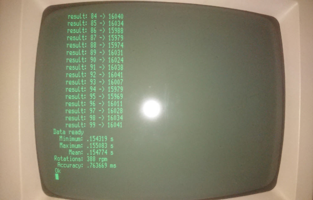
I measured the rotation 100 times, the numbers are consistent. However, I’m still at 388rpm, which is too high for a real floppy drive. I’m definitely missing here something. The floppy drive is working, so I don’t think, the numbers are correct.
Comments
No comments yet.Leave a comment
Your email address will not be published. Required fields are marked *. All comments are held for moderation to avoid spam and abuse.