Repairing Hyundai W240D monitor
Introduction
My monitor is a Hyundai W240D. It is very old, but still working. It’s a 24” full hd monitor and I bought it in January 2008. So it is now 15 years old. It had some problem with the backlight after about 1 year - but that was repaired during warranty. After that, no problems. Until a couple of weeks ago, I noticed, that it has some signal faults. It seems to be happening more frequently, after the monitor was powered on for a while (which makes it maybe a temperature problem). And it also depends on the image, that is displayed - so, e.g. switching from full screen to window or so, sometimes helped a bit, in order to “calm down” my monitor. But that’s not a solution. It become increasingly annoying. It could even be as bad, that the monitor didn’t update the picture for a while and the LCD lost it’s color… until a next full frame was successfully painted - or at least part of it.
So, what to do? One way could be - well 15 years is not bad. Maybe it’s time for a new monitor with higher resolution. But - when researching to understand the problem, I found a ifixit article about this monitor:
https://de.ifixit.com/Anleitung/Hyundai+W241D+Defekte+Kondensatoren+tauschen+bei+Bildflackern/122910
It’s in German and it has nice pictures of what to do.
So I decided to give it a try. Worst case, I’d need to buy a new monitor.
First opening
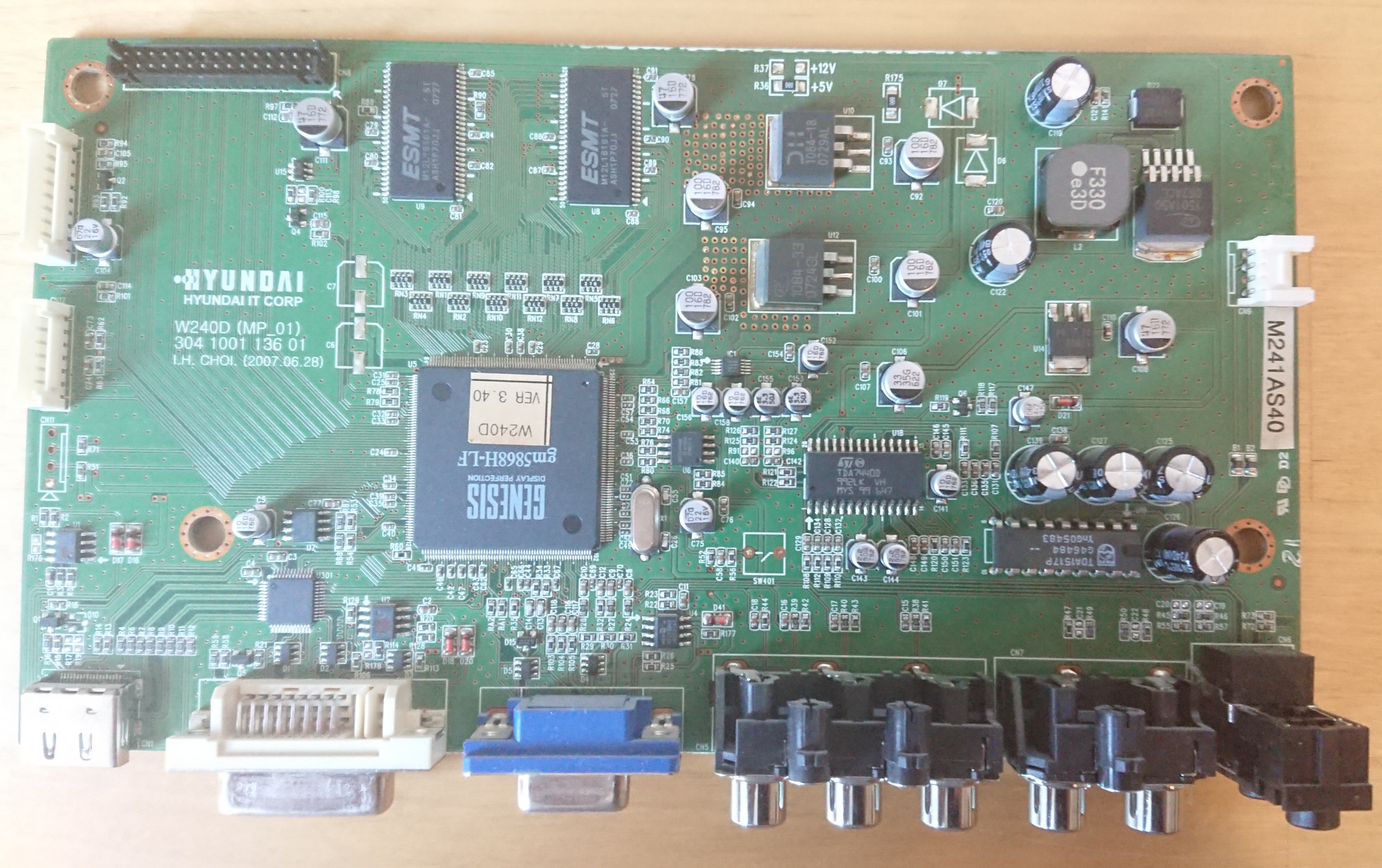
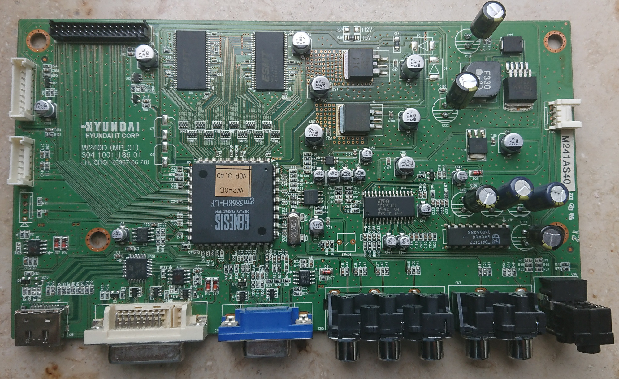
I first opened the monitor and verified, that I could find the capacitors, that are maybe old and need replacement. Since the ifixit instruction is for a slightly different model W241D than I have (W240D), I wanted to be sure. And yes, it looks exactly the same. In the ifixit instruction, you can actually see, that it is actually a W240D model - there is a sticker on the board.
So, that’s good. I verified also, that I have exactly the same caps at the same place, so I can order new ones.
Measuring capacitance
Once the new caps arrived, I wanted to measure them. My goal was, to be able to say in the end: These caps were bad, and these were good. So I took my multi meter, which has a capacitance meter built in and tried it.
However, my multimeter only can measure caps up to around 100µF. But the caps I want to replaces are e.g. 220µF. At first I was puzzled until I figured out - yes. My multimeter is not capable to measuring such big caps. But I still want to compare the new caps and the old caps.
I remember, capacitors have a specific loading curve and after researching a bit more, I also found it. You could use a oscilloscope and measure the time, how long it takes to load the cap. Or unload. I tried it - you basically see the graph, but with my DIY oscilloscope it would be a bit tedious to measure the capacitance that way.
Researching a bit more, there are interesting solutions, like a small circuit which keeps an led powered until the cap is unloaded. You can then measure, how long the led was illuminated and that gives you how many Farads the capacitor has. This is described here: https://www.weltderfertigung.de/suchen/lernen/elektronik/kondensatoren-clever-pruefen.php. The bigger the capacitor, the longer the led is on.
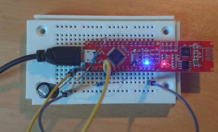
This would required a small circuit. Researching further, I found an article from the German maker magazine “Make”: https://make-magazin.de/xzew. If you search for the title “Arduino-Messgerät für Kondensatoren” you might be lucky and find the article for free. It is based on an arduino sketch to measure the capacitance: https://docs.arduino.cc/tutorials/generic/capacitance-meter.
They extended the sketch to include a basic ESR measurement as well. It’s explained in the article: They measure the voltage immediately after starting loading. They estimate, that this would be about 200µs (that’s the delay the arduino takes to actually read the analog value and convert it into digital ADC). They compare the measure voltage at this time with the voltage of an ideal capacitor (without resistance, 0 Ohm ESR). If it is higher, then the difference is the ESR of the cap. That’s very rough, but is enough to find caps with big ESR.
Luckily, I have an arduino nano, so I can use this. Getting the sketch to work properly was again a challenge. Using https://iot.fkainka.de/pinout-pretzel-board-nanoesp I figured out, that D13 is connected to the LED on the board, so better to use another pin for charging. And I made wrong assumptions about the wiring of the breadboard, so I first shorted everything and wondered, why the capacitor wasn’t loading at all… In the end, I got it working. And it’s really much easier than using the oscilloscope.
With that setup, I could verify, that the new ordered caps are in good shape and they all measured with 0 Ohm ESR.
Replacing
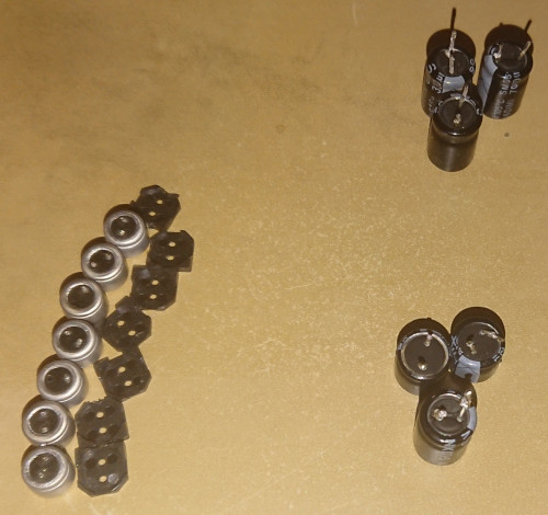
Time to replace the caps. I started with the through hole caps which had 330µF and 470µF and 220µF. It was a bit hard to melt the old solder (I probably used a wrong solder iron). But eventually I got them loose. Ideally you would cleanly desolder the hole using a desolder pump (which I don’t own). So I gave up free up the holes and just put the caps an little legs - hoping that doesn’t matter too much.
Since I couldn’t get the SMD caps desoldered, I didn’t change them. I hoped, these caps are maybe enough. I closed the monitor and gave it a try.
I replaced in total 6 THT caps. Half of them were good, the other half had an ESR > 0 Ohm. The capacitance was however not too bad - if 20% tolerance is accepted. Here are the measurements:
470µF
19:42:14.473 -> (4501 ms); 450 mikro F ; ESR: 30 Ohm
19:42:48.775 -> (4923 ms); 492 mikro F ; ESR: 90 Ohm
19:42:58.524 -> (4917 ms); 491 mikro F ; ESR: 20 Ohm
19:43:08.472 -> (4913 ms); 491 mikro F ; ESR: 20 Ohm

220µF
19:47:25.668 -> (2004 ms); 200 mikro F ; ESR: 140 Ohm
19:47:32.255 -> (2000 ms); 200 mikro F ; ESR: 100 Ohm
19:47:38.892 -> (1974 ms); 197 mikro F ; ESR: 100 Ohm

220µF
19:48:10.004 -> (1908 ms); 190 mikro F ; ESR: 120 Ohm
19:48:16.491 -> (1802 ms); 180 mikro F ; ESR: 90 Ohm
19:48:23.010 -> (1873 ms); 187 mikro F ; ESR: 90 Ohm
19:48:29.564 -> (1908 ms); 190 mikro F ; ESR: 90 Ohm
19:48:35.985 -> (1822 ms); 182 mikro F ; ESR: 90 Ohm
Unfortunately, the flickering came back after a while. So, I needed to replace the SMD caps as well. Since desoldering them didn’t work with my cheap tooling (I bought a tweezer, but somehow still couldn’t bring both sides to melt to lift the cap), I decided to be brave and use the “turn around to remove the cap” way. Essentially it breaks the legs of the cap and it hopefully doesn’t destroy the pads. And for me, it didn’t. The plastic bottom usually stays on the board but can be removed easily. Part of the legs stay on the pad and should be desoldered, if possible, to have clean pads for the new caps.
These were 7 SMD caps I removed. Since the legs are broken, it was a fiddle to measure them and the connection was probably not so good, which might add some resistance. But here are the measurements for them:
100µF
19:56:49.687 -> (954 ms); 95 mikro F ; ESR: 90 Ohm
19:56:55.142 -> (946 ms); 94 mikro F ; ESR: 60 Ohm
19:57:00.500 -> (966 ms); 96 mikro F ; ESR: 60 Ohm

47µF
20:01:09.354 -> (463 ms); 46 mikro F ; ESR: 60 Ohm
20:01:14.206 -> (460 ms); 46 mikro F ; ESR: 50 Ohm
20:01:19.031 -> (454 ms); 45 mikro F ; ESR: 50 Ohm
20:01:23.852 -> (462 ms); 46 mikro F ; ESR: 60 Ohm

47µF
20:01:45.250 -> (627 ms); 62 mikro F ; ESR: 340 Ohm
20:01:50.074 -> (482 ms); 48 mikro F ; ESR: 230 Ohm
20:01:54.688 -> (340 ms); 34 mikro F ; ESR: 220 Ohm
20:02:40.453 -> (465 ms); 46 mikro F ; ESR: 280 Ohm
20:02:45.210 -> (472 ms); 47 mikro F ; ESR: 150 Ohm

100µF
20:03:19.865 -> (920 ms); 92 mikro F ; ESR: 390 Ohm
20:03:25.188 -> (912 ms); 91 mikro F ; ESR: 320 Ohm
20:03:30.640 -> (952 ms); 95 mikro F ; ESR: 310 Ohm
20:03:36.130 -> (955 ms); 95 mikro F ; ESR: 300 Ohm

100µF
20:03:58.115 -> (997 ms); 99 mikro F ; ESR: 90 Ohm
20:04:03.571 -> (975 ms); 97 mikro F ; ESR: 60 Ohm
20:04:09.060 -> (990 ms); 99 mikro F ; ESR: 50 Ohm

47µF
20:06:14.749 -> (476 ms); 47 mikro F ; ESR: 320 Ohm
20:06:31.986 -> (476 ms); 47 mikro F ; ESR: 110 Ohm
20:06:36.875 -> (477 ms); 47 mikro F ; ESR: 150 Ohm

100µF
20:11:31.262 -> (903 ms); 90 mikro F ; ESR: 80 Ohm
20:11:36.649 -> (961 ms); 96 mikro F ; ESR: 80 Ohm
20:11:42.103 -> (962 ms); 96 mikro F ; ESR: 160 Ohm
All the SMD caps had a ESR > 0 Ohm. The capacity is still according to the spec. But the ESR is a bit big. It should be in the milli ohm range, up to a few Ohms. But not 60 or even 300.
So I guess, there were indeed some bad caps.
Conclusion
At least, I didn’t make it worse. As I’m writing this post, I’m already using my monitor with the replaced caps. Till now, I didn’t see any problems. But I’ll need to observe this for some more days.
Interesting is, that the capacitance was still there. So, it seems, the caps have not yet dried out. But the ESR was raising. Probably due to old age and temperature. I noticed, the monitor is really getting warm, so the suggested 105°C rating is probably needed.
While 3 caps seem okish according to my simple measurements, it’s probably not a good idea to use them for real applications anymore. They have plenty of hours behind them with much heat, so they will probably fail rather sooner than later anyway.
Maybe capacitor reforming could rescue them as well? Read more about this here: https://hackaday.com/2023/06/05/protect-vintage-gear-with-easy-capacitor-reforming/.
But for now, I think the repair was a success!
Fun with EDID
cat /sys/class/drm/card0/card0-DP-1/edid | parse-edid gives this
	Identifier "W240D DVI"
	ModelName "W240D DVI"
	VendorName "HIT"
	# Monitor Manufactured week 30 of 2007
According to https://en.wikipedia.org/wiki/Extended_Display_Identification_Data
and cat /sys/class/drm/card0/card0-DP-1/edid | hd:
00000000  00 ff ff ff ff ff ff 00  21 34 03 7d 43 41 32 01  |........!4.}CA2.|
00000010  1e 11 01 03 80 34 20 78  0a ef 95 a3 54 4c 9b 26  |.....4 x....TL.&|
00000020  0f 50 54 ad cf 00 d1 00  a9 40 b3 00 81 80 01 01  |.PT......@......|
00000030  01 01 01 01 01 01 28 3c  80 a0 70 b0 23 40 30 20  |......(<..p.#@0 |
00000040  36 00 08 40 21 00 00 1a  48 3f 40 30 62 b0 32 40  |6..@!...H?@0b.2@|
00000050  40 c0 13 00 08 40 21 00  00 1e 00 00 00 fd 00 3b  |@....@!........;|
00000060  4c 1e 53 12 00 0a 20 20  20 20 20 20 00 00 00 fc  |L.S...      ....|
00000070  00 57 32 34 30 44 20 44  56 49 0a 20 20 20 01 33  |.W240D DVI.   .3|
00000080  02 03 1c 71 49 90 14 13  12 05 04 03 02 01 23 09  |...qI.........#.|
00000090  07 07 83 01 00 00 65 03  0c 00 10 00 8c 0a d0 90  |......e.........|
000000a0  20 40 31 20 0c 40 55 00  13 8e 21 00 00 18 01 1d  | @1 .@U...!.....|
000000b0  80 18 71 1c 16 20 58 2c  25 00 c4 8e 21 00 00 9e  |..q.. X,%...!...|
000000c0  01 1d 00 72 51 d0 1e 20  6e 28 55 00 c4 8e 21 00  |...rQ.. n(U...!.|
000000d0  00 1e 8c 0a d0 8a 20 e0  2d 10 10 3e 96 00 c4 8e  |...... .-..>....|
000000e0  21 00 00 18 8c 0a d0 8a  20 e0 2d 10 10 3e 96 00  |!....... .-..>..|
000000f0  13 8e 21 00 00 18 00 00  00 00 00 00 00 00 00 c4  |..!.............|
The manufacturer id is 2134, which gives 01000, 01001, 10100, which is indeed “HIT”.
This is according to https://uefi.org/PNP_ID_List?search=HIT the company “Hitachi America Ltd”
and not Hyundai…
Update
I’ve done the repair in June 2023 and till now (December 2023) the monitor works like a charm. So, this still is a success!
Comments
No comments yet.Leave a comment
Your email address will not be published. Required fields are marked *. All comments are held for moderation to avoid spam and abuse.