RS-232 physical serial signals
Introduction
When interfacing a serial port, which works according to the RS-232 standard, one should be careful: The signal levels are not the TTL-like 5V, but could be much higher or lower. If you connect a microcontroller directly to a RS-232 without a line driver/receiver, then you could damage your microcontroller.
After checking the standard, I’m going to measure the actual voltages, that some common USB-to-Serial converters use. I was curious, whether these converters really are RS-232 compatible. They are powered via USB, so they have a main power source with 5V…
RS-232 standard
The standard defines a common ground (GND) signal line, which is connected between the DTE (data terminal equipment, e.g. a computer) and DCE (data communications equipment, e.g. modem). In case a nullmodel cable is used, then the ground of the two computers is connected. This is a so called ground loop and effectively limits the length of the cable. It might also be dangerous for the chips, as two computers far apart from each other powered by different power sources might have a totally different ground level and through this ground loop, current will flow - and maybe too much current, which can damage the devices. However, this is not a problem as long as the two computers are relatively near to each other (same room, same floor).
All voltage levels are relative to this common ground. RS-232 defines data lines (RxD, TxD) and control lines (e.g. DTR, DSR, RTS, CTS). It defines two voltage levels, which represent the two states of the lines. Actually, not exact voltage levels, but voltage ranges are defined:
- +3V to +15V
- -3V to -15V
Any voltage between -3V and +3V is undefined. The longer the cable, the more loss can be expected, so putting in +15V in one end, might result in a slightly lower voltage at the other end. RS-232 driver chips usually produce a certain voltage. Let’s assume for now, the chips will simply use +15V/-15V, but will still receive signals with only +5V/-5V correctly when receiving.
For the control lines, a positive logic is used: An asserted control line uses e.g. +15V, a deasserted control line is at -15V.
The data lines use by contrast a negative logic: a logical “0” is +15V and a logical “1” is -15V. The logical “0” is also called a “space” and a logical “1” is called a “mark”.
The table on the wikipedia article on RS-232#Physical interface perfectly summarizes this:
| Data circuits | Control circuits | Voltage |
|---|---|---|
| 0 (space) | Asserted | +3 to +15V |
| 1 (mark) | Deasserted | -3 to -15V |
The standard also demands, that the RS-232 chips must be able to cope with short-circuit situations. E.g. connections from any signal to ground or to any voltage level up to 25V.
As we see, the voltage levels could be significantly higher than the voltages used by typical microcontrollers (3.3V or 5V). That’s why the interface on the microcontroller side is not called “RS-232” but “UART”. In order to add a RS-232 compatible interface to a microcontroller, one needs to add a line driver chip, such as MAX232. This will convert the 5V of the microcontroller (or 3.3V) to the desired voltage for RS232 (e.g. 15V/-15V).
You can’t connect the microcontroller directly, although it seems to be in the correct physical range (+3.3V or 5V) for a “0”. The reason is that you can’t put “-3.3V” on the line that way…
The line driver not only provides the correct voltage levels, it also inverts the logic for the data lines and protects the microcontroller from too high voltages and short circuits.
Break condition
The RS232 connection has a possibility to detect, if one end suddenly disconnects. E.g. when the cable breaks or shorts with any other signal.
The TxD line is typically kept in mark level (logical 1, below -3V) when no transmission occurs. This is the idle state. The start of a transmission is signalled with the start bit, which goes from logical 1 to 0 (from mark to space). When the TxD line is for longer than one characters time (so all this depends on the baud rate) in space level (logical 0, above +3V), then this is detected as a “break condition”.
According to Wikipedia USART the term “break” comes literally from indicating that the cable is broken.
Today, the break condition is used as some kind of in-band signalling to the receiver, e.g. to reset. It might also indicate different error conditions like mismatched baud rates. See also What does BREAK mean in real terms while using a UART?.
Power source
In the old days, we had mouse devices that were using the serial port - so RS232. These mice didn’t need any batteries or so, they were powered through the serial port. But how? There are no signals that are dedicated for sending power to devices.
But two signal lines can be used to “harvest” small amounts of power: DTR and RTS lines. There is an application note for a PC mouse, which explains this in detail: AN-681 PC Mouse Implementation Using COP800. Here’s a quote:
Since the serial port of the PC has no power supply lines, the RTS, CTS, DTR and DSR RS232 interface lines are utilized. Therefore the microcontroller and the mouse hardware should have very little power consumption. National Semiconductor’s COP822C fits into this category perfectly. The voltage level in the RS232 lines can be either positive or negative. When they are positive, the power supply can be obtained by clamping down with diodes. When they are negative, a 555 timer is used as an oscillator to transform the voltage level to positive. The 1988 National Semiconductor Linear 3 Databook has an example of how to generate a variable duty cycle oscillator using the LMC555 in page 5-282.
While the RTS and DTR lines are used to provide the voltage for the mouse hardware, the TXD line of the host is utilized as the source for the communication signals. When idle, the TXD line is in the mark state, which is the most negative voltage. A pnp transistor can be used to drive the voltage of the RXD pin to a voltage level that is compatible with the RS232 interface standard.
Neat: Since the communication is basically a one-way (from the mouse to the PC), the PC is keeping the TXD line in idle (mark) state always.
There is another article about using RS-232 as power source: Get power out of PC RS-232 port. You should be ok, if you circuitry doesn’t consume more than 5-10mA @ 5V - which gives about 25mW-50mW. This assumes using both DTR+RTS lines.
This question talks about having DTR asserted and RTS unasserted, which gives a total of 24V difference: How can RS-232 DTR / RTS pins be used for power?.
The next article claims that “most RS232 driver IC’s are capable to deliver at least 45 mA”. Which would be much more. This article is about the circuitry of a simple RS-232 sniffer: RS232 serial spy monitor cable. This is cited again in this question RS232 output current rating.
A very simple solution is the one used in DCF77 Pollin – Serial: It uses DTR (pin 4) just connected to a voltage regulator. That’s it.
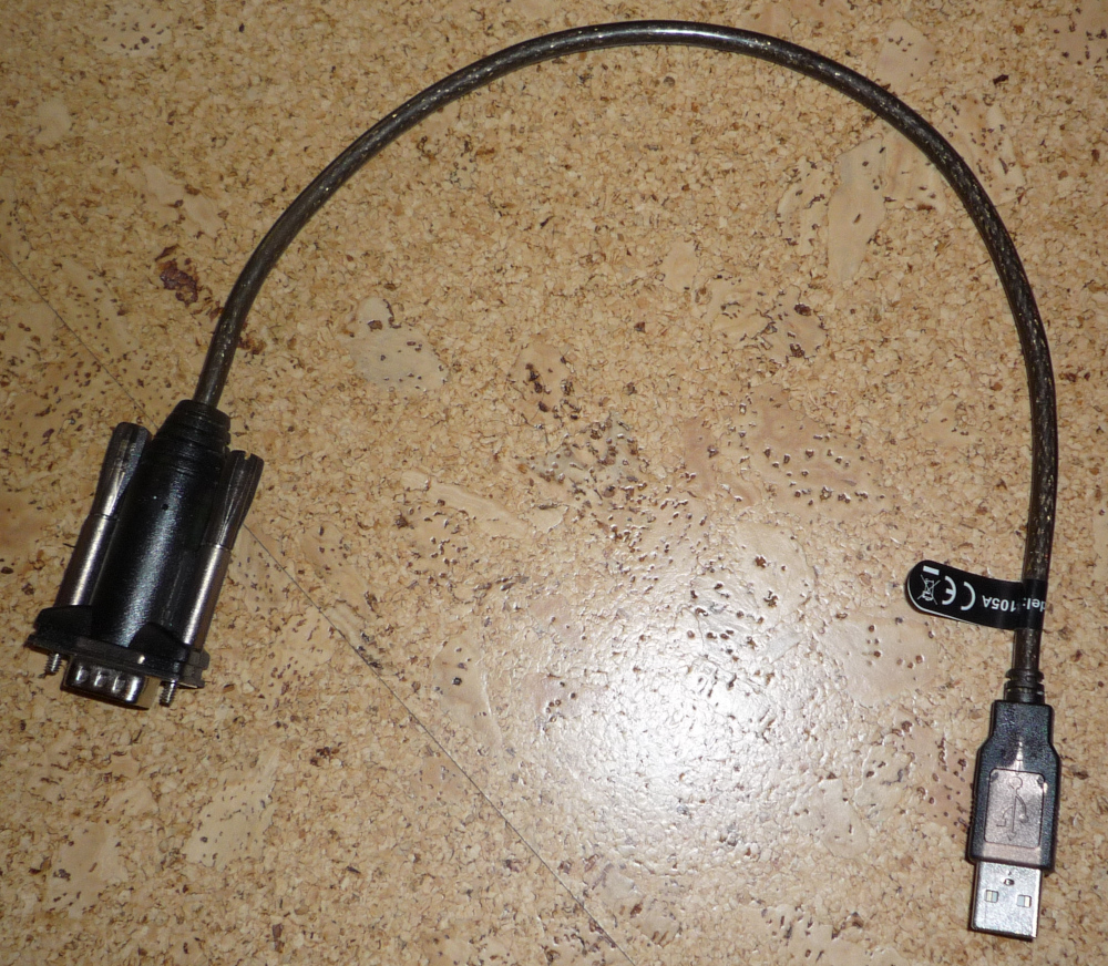
UART modules
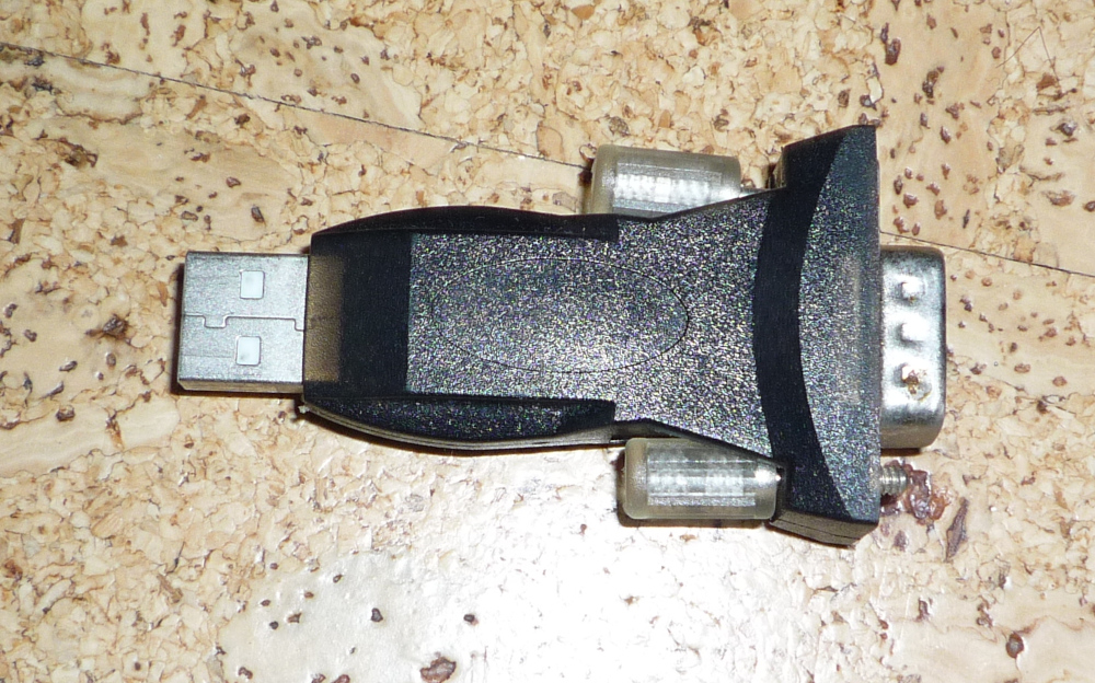
Since I have a couple of USB converter modules, I want to know, with which voltages they work. So I hooked up my DIY DSO 068 oscilloscope to the RS-232 connector using some jumper wires. Actually I connected a loop, that means, I directly connected TxD to RxD, so that the RS-232 chip immediately receives what it transmits. Like an echo.
Here’s a picture of that “test setup”:
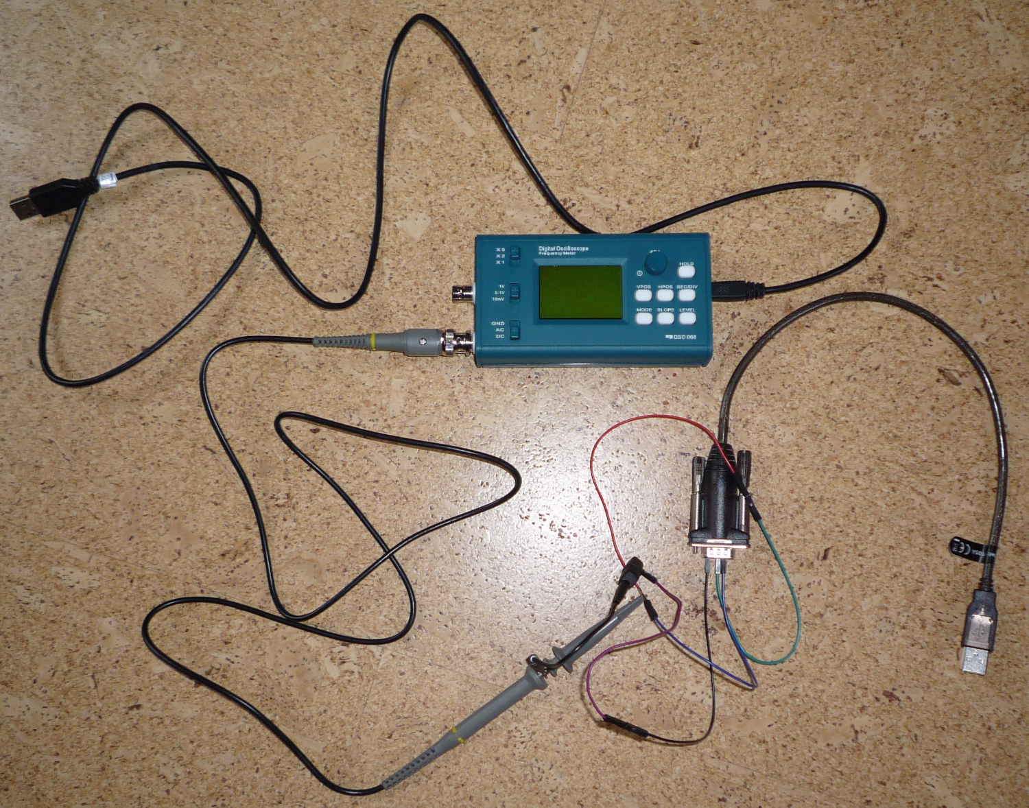
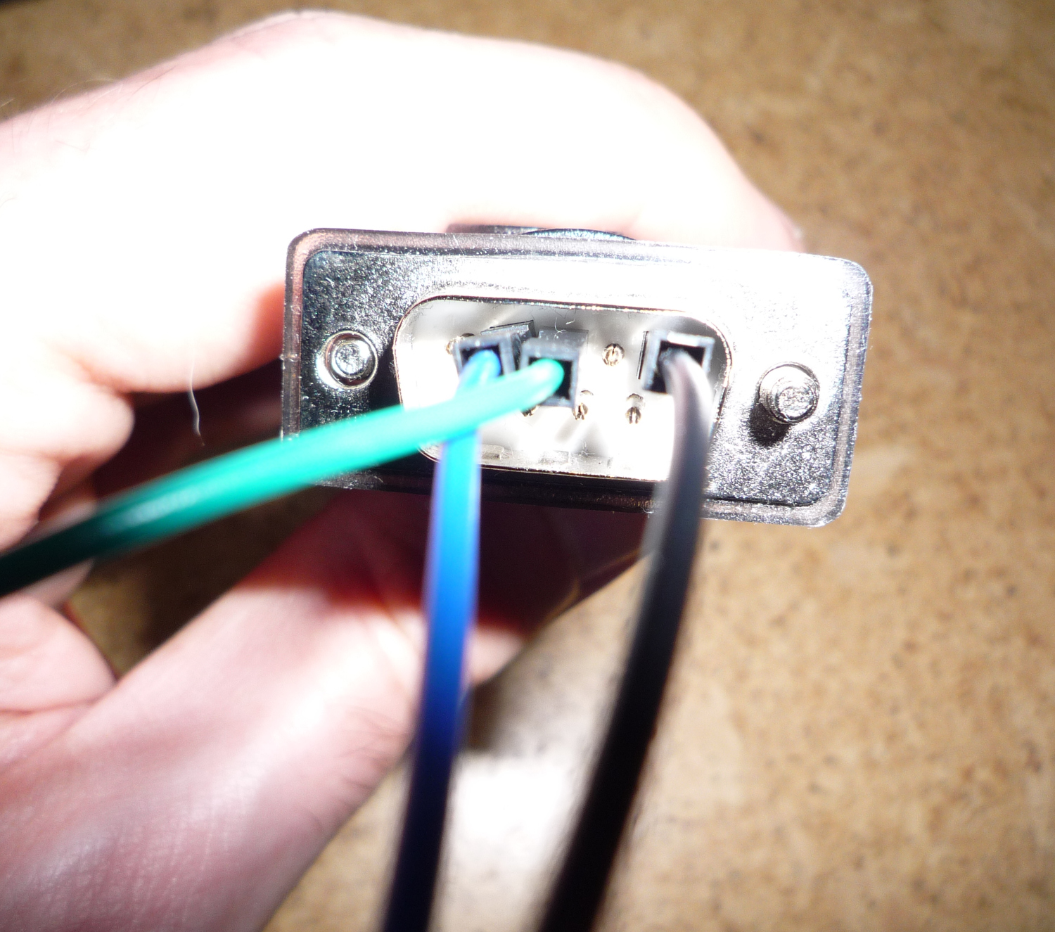
As you can see, I connected pin 5 (GND, black wire) and pin 2/3 (TxD/RxD, green and blue wire). The green and blue wires are connected to each other via a red wire. The black ground wire has been extended by a pink wire.
Once the USB converter is plugged in, sending data is as simple as
stty -F /dev/ttyUSB0 4800
echo -n "U" > /dev/ttyUSB0
This sets the baudrate and sends two characters. I used “U”, because the ASCII code of that letter is 0x55, which is in binary “0101 0101”. That is a nice repeating pattern.
I also used the letters “a”, “A”, “aa”, “u”, “U”, and “uu”.
You could also use any terminal program to send these. Important is, that we see some movement of the signals on the wire.
I always used the setting 4800 baud, 8-n-1. For the DSO, I used the probe with 10x setting. That’s important to read the actual voltage levels.
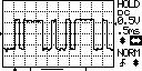
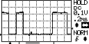
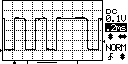
USB converter Prolific
USB identification: ID 067b:2303 Prolific Technology, Inc. PL2303 Serial Port / Mobile Action MA-8910P
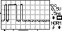
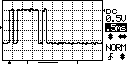
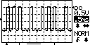
The signal spans a bit more than 3 squares. Each square is 5V (10x0.5V). The 0 point is roughly in the middle, that means, the signal goes from about -8V to +8V.
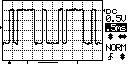
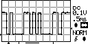
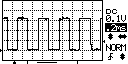
USB converter FT232
USB identification: ID 0403:6001 Future Technology Devices International, Ltd FT232 Serial (UART) IC
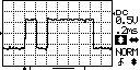
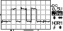
The signal spans almost 3 squares, roughly from -7V to +7V.
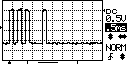
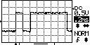
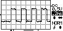
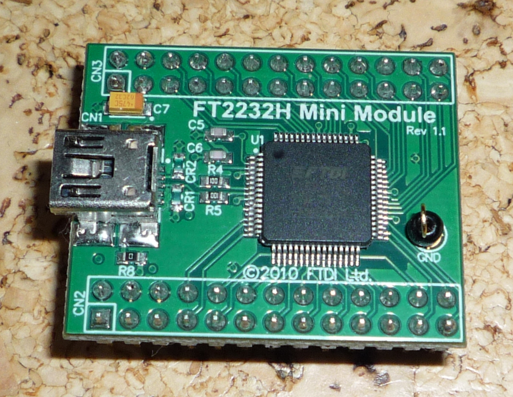
FTDI FT2232H MiniModule
As a comparison, the mini module without a line driver. The outputs should be TTL level (or below) and not be negative volts.
USB identification: ID 0403:6010 Future Technology Devices International, Ltd FT2232C/D/H Dual UART/FIFO IC
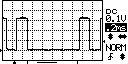
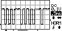
One square is now 1V (10x 0.1V). The signal spans a bit more than 3 squares. The 0 point is at the bottom, so no negative voltages. The signal spans from 0V to +3.2V.
The the voltage levels are inverted, e.g. in idle the line is at 3.2V, which is a logic 1.
Summary
So the RS232 really use voltages above 5V and are dangerous to directly connect to a microcontroller directly. The voltage levels are within spec and range from -7/-8V to +7/+8V.
References
- https://en.wikibooks.org/wiki/Serial_Programming/RS-232_Connections
- https://en.wikipedia.org/wiki/RS-232#Physical_interface
- https://en.wikipedia.org/wiki/Ground_loop_(electricity)
- https://en.wikipedia.org/wiki/Universal_asynchronous_receiver-transmitter#Break_condition
- https://stackoverflow.com/questions/37540293/what-does-break-mean-in-real-terms-while-using-a-uart
- AN-681 PC Mouse Implementation Using COP800
- Get power out of PC RS-232 port
- How can RS-232 DTR / RTS pins be used for power?
- RS232 serial spy monitor cable
- RS232 output current rating
- DCF77 Pollin – Serial
Comments
No comments yet.Leave a comment
Your email address will not be published. Required fields are marked *. All comments are held for moderation to avoid spam and abuse.