Alphatronic P2 speed follow-up 2
This is one additional follow up. As figured out in the last post, the used memory chips (ROM and RAM) on the CPU card are likely fast enough to be used without a wait state. So the idea is, to run my tone generator and maybe the floppy drive rotation measurement in the RAM on the CPU card.
Memory map
The RAM on the CPU card is 1kB. This should be big enough for my small programs. However, this RAM is used by the MOS (Mikrocomputer Operating System), so overwriting data in there might destroy some data structures. But that’s ok, then I just need to reset the whole PC again, and it should work again.
The memory map of the Alphatronic P2 is given in the following picture:
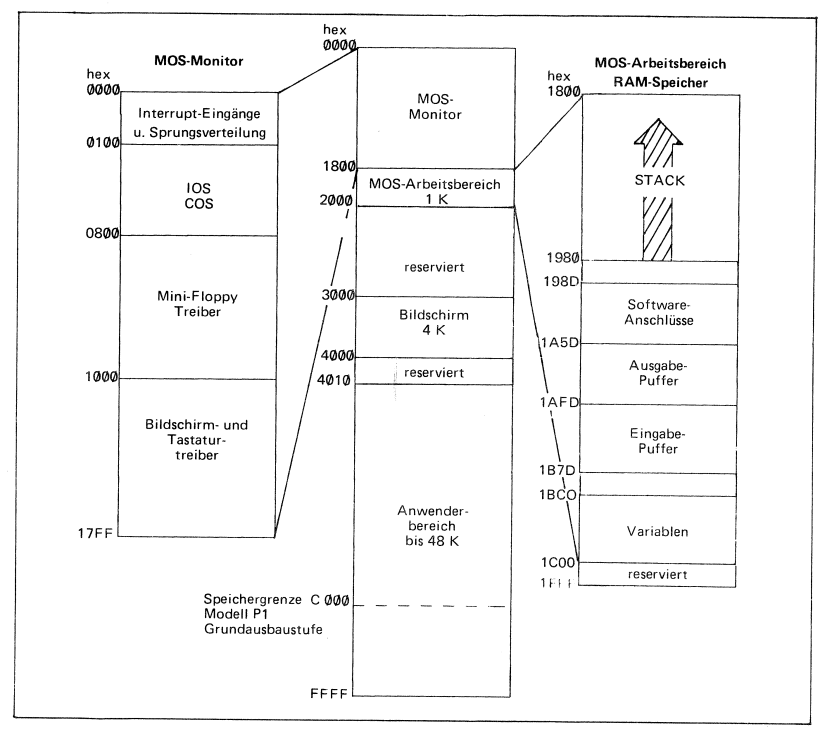
The 1kB RAM on the CPU card begins at address 0x1800 and ends with 0x1BFF. The range from 0x1C00 to 0x1FFF seems to be unmapped and unusable.
The “Tone Generator” machine program requires 59 bytes (0x3B). The stack of the MOS starts at 0x1980 and grows up to 0x1800. So let’s just use the range 0x1800 to 0x183B for our program…
The adjusted “Tone Generator” v4
We need to adjust the program from Measuring CPU speed and change the jumps to be in the correct address space. The counters stay as they are - so the loop should be repeated 243 (0xF3) times.
; address       machine code    mnemonic        comments
1800            06 05           MVI B, 5H
1802    G       0E DC           MVI C, DCH      ; 0xDC=220
1804    C       3E 01           MVI A, 1H
1806            D3 12           OUT 12H         ; 0x12=18
1808            16 F3           MVI D, F3H      ; 0xF3=243
180A    A       15              DCR D
180B            C2 0A 18        JNZ A           ; A -> 0x180A
180E            3E 00           MVI A, 0H
1810            D3 12           OUT 12H         ; 0x12=18
1812            16 F3           MVI D, F3H      ; 0xF3=243
1814    B       15              DCR D
1815            C2 14 18        JNZ B           ; B -> 0x1814
1818            0D              DCR C
1819            C2 04 18        JNZ C           ; C -> 0x1804
181C            0E DC           MVI C, DCH      ; 0xDC=220
181E    F       3E 00           MVI A, 0H
1820            D3 12           OUT 12H         ; 0x12=18
1822            16 F3           MVI D, F3H      ; 0xF3=243
1824    D       15              DCR D
1825            C2 24 18        JNZ D           ; D -> 0x1824
1828            3E 00           MVI A, 0H
182A            D3 12           OUT 12H         ; 0x12=18
182C            16 F3           MVI D, F3H      ; 0xF3=243
182E    E       15              DCR D
182F            C2 2E 18        JNZ E           ; E -> 0x182E
1832            0D              DCR C
1833            C2 1E 18        JNZ F           ; F -> 0x181E
1836            05              DCR B
1837            C2 02 18        JNZ G           ; G -> 0x1802
183A            C9              RET
The BASIC program to load this also looks a bit different. We don’t need the CLEAR statement
anymore, since we don’t put it into the memory space of the BASIC interpreter anymore. The CLEAR
statement made space for us by moving some data structure of the BASIC interpreter out of the way.
100 PRINT "Tone Generator V4"
110 I=&H1800
120   READ D$
130   D=VAL("&H"+D$)
140   IF D>255 THEN GOTO 500
150   POKE I,D
160   I=I+1
170 GOTO 120
200 DATA 06,05,0E,DC,3E,01,D3,12,16,F3,15,C2,0A,18,3E,00,D3,12
210 DATA 16,F3,15,C2,14,18,0D,C2,04,18,0E,DC,3E,00,D3,12,16,F3
220 DATA 15,C2,24,18,3E,00,D3,12,16,F3,15,C2,2E,18,0D,C2,1E,18
230 DATA 05,C2,02,18,C9
490 DATA E0F
500 I=&H1800
510 CALL I
The results
The resulting video:
If you analyze the audio, you’ll find that the tones are now about 1 second apart and closer to 440 Hz.
Bonus: Floppy Drive rotation
The original program from Measuring Floppy Drive rotation speed - Part 2 also needs some adjustments. It’s size is even smaller, it only needs 30 (0x1E) bytes. Here it is:
                                       ORG     1800H
                                       PUBLIC  READ_INDEX_DURATION
1800'  3E D4      READ_INDEX_DURATION: MVI     A,D4H    ;FORCE-INTERRUPT command with IP (index pulse)
1802'  D3 50                           OUT     50H      ;execute command
1804'  06 40                           MVI     B,40H    ;Mask for index detected flag in status register
1806'  11 0000                         LXI     D,0      ;init counter in D
1809'  DB 50                           IN      50H      ;reading the command register?? apparently clearing the IRQ flag
180B'  DB 54                   LOOP1:  IN      54H      ;reading status register into A
180D'  A0                              ANA     B        ;check if index is set
180E'  CA 0B18'                        JZ      LOOP1    ;if no index yet, busy wait...
1811'  DB 50                           IN      50H      ;clearing the INDEX flag for next index detection
1813'  13                      LOOP2:  INX     D        ;counting now...
1814'  DB 54                           IN      54H      ;reading status register into A
1816'  A0                              ANA     B        ;check if index is set
1817'  CA 1318'                        JZ      LOOP2    ;jump back, if no index and keep counting
181A'  73                              MOV     M,E      ;copy counter (low Byte) to memory at [H]
181B'  23                              INX     H        ;
181C'  72                              MOV     M,D      ;copy counter (high Byte) to memory at [H]
181D'  C9                              RET
And the BASIC program:
100 '************** DRIVEROT4
110 DEFINT D
120 GOSUB 500
130 PRINT"In the last used drive a floppy has to be inserted!"
140 INPUT"How many measurements should be taken?"; COUNT
150 DIM DAT%(COUNT)
160 FOR D=0 TO COUNT-1
170     PRINT"  Start measurement ";D
180     CALL RID(LOOPS%)
190     DAT%(D)=LOOPS%
195     PRINT"    result:";D;"->";DAT%(D)
200 NEXT
210 PRINT"Data ready"
220 MIN=DAT(0) :MAX=MIN :SUM=0
230 FOR D=0 TO COUNT-1
240     IF DAT(D)<MIN THEN MIN=DAT(D)
250     IF DAT(D)>MAX THEN MAX=DAT(D)
260     SUM=SUM+DAT(D)
270 NEXT
280 MEAN=SUM/COUNT
290 LPS=103448! 'loops per second: 3 MHz/29 cycles - dur. of one loop
300 RPM=INT(60*LPS/MEAN+.5)
310 DIF=MAX-MIN
320 PRINT"  Minimum:";MIN/LPS;"s"
330 PRINT"  Maximum:";MAX/LPS;"s"
340 PRINT"     Mean:";MEAN/LPS;"s"
350 PRINT"Rotations:";RPM;"rpm"
360 PRINT" Accuracy:";DIF*1000/LPS;"ms"
370 END
500 ' Machine program RID (=read_index_duration)
510 I=&H1800
520 RID=&H1800
530    READ D$
540    D=VAL("&H"+D$)
550    IF D>255 THEN RETURN
560    POKE I,D
570    I=I+1
580 GOTO 530
590 DATA 3E,D4,D3,50,06,40,11,00,00,DB,50,DB,54
600 DATA A0,CA,0B,18,DB,50,13,DB,54,A0,CA,13,18
610 DATA 73,23,72,C9,E0F
The result is pretty impressive:
RUN
In the last used drive a floppy has to be inserted!
How many measurements should be taken?? 10
  Start measurement  0
    result: 0 -> 20287
  Start measurement  1
    result: 1 -> 20222
  Start measurement  2
    result: 2 -> 20552
  Start measurement  3
    result: 3 -> 20778
  Start measurement  4
    result: 4 -> 20696
  Start measurement  5
    result: 5 -> 20396
  Start measurement  6
    result: 6 -> 20640
  Start measurement  7
    result: 7 -> 20652
  Start measurement  8
    result: 8 -> 20389
  Start measurement  9
    result: 9 -> 20443
Data ready
  Minimum: .19548 s
  Maximum: .200855 s
     Mean: .19822 s
Rotations: 303 rpm
 Accuracy: 5.37468 ms
Ok
This was the measurement on the real floppy drive: 303rpm. That’s basically valid. I also measured it on the GoTek floppy emulator: 310rpm. A bit too high, it should be exactly 300rpm. But ok.
Upper memory
I’ve had a close look again at the memory card and I’ve now found a connection to the READY-signal. Although I don’t know exactly, how it is connected - at least it seems to be used.
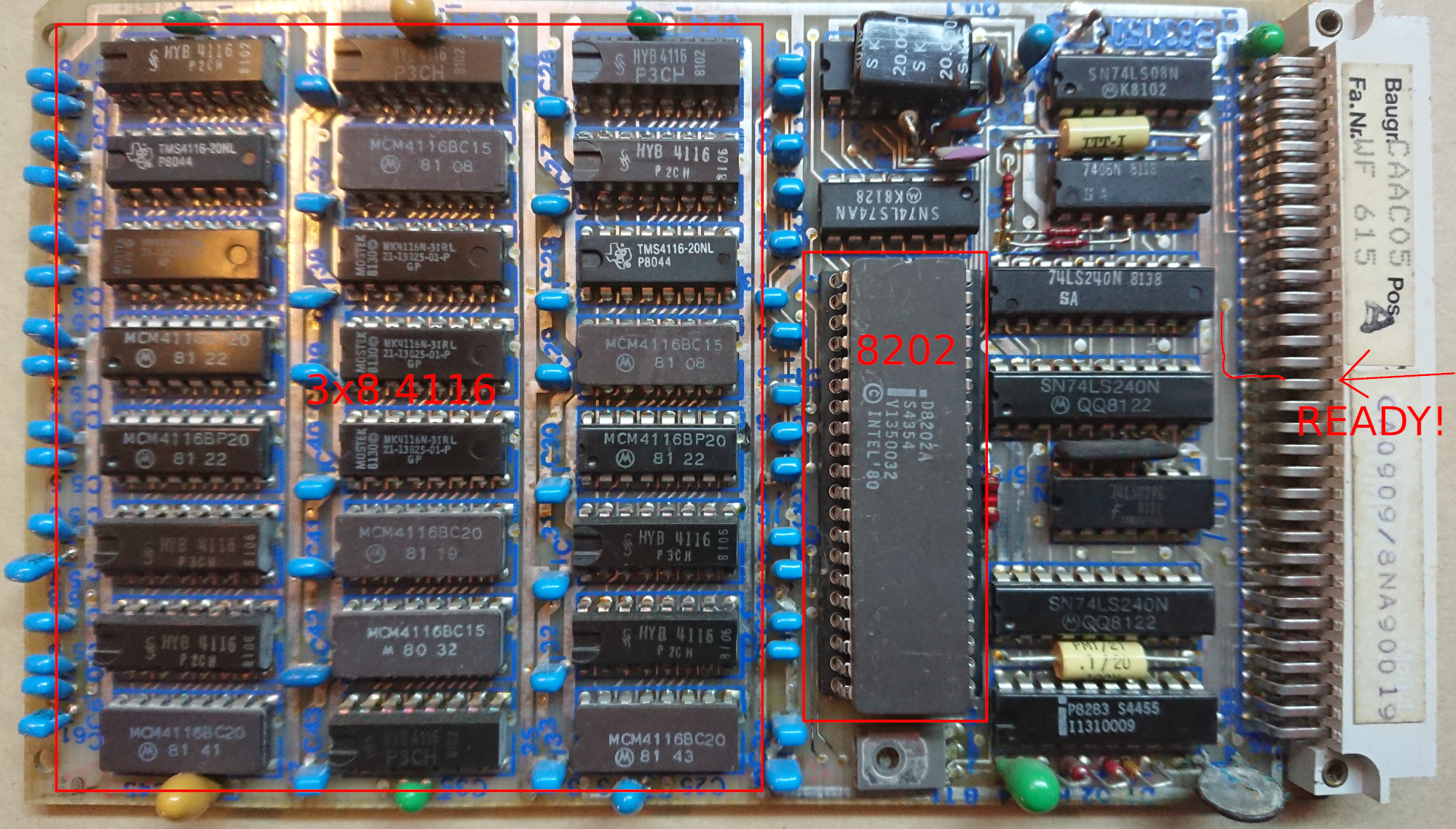
The card uses a 8202 Dynamic RAM controller to refresh the 24 chips on the left. Each of these chips is a 4116 and stores 16384 bit of memory (2048 bytes). In total, this card provides 48kB of RAM.
There is another card, that contains 16kB of RAM. So it seems that my Alphatronic is not the model P2 but the model P2U. This has the ability to use full 64kB of RAM with the help of bank switching.
The memory map explains, that the 48kB card is mapped from 0000 to BFFF. However, the lower part from 0000 to 3FFF is used by the ROM chips to provide the MOS. The 16kB card is added from C000 to FFFF. With the bank switch one can remove the MOS and use the lower part of the 48kB card from 0000 to 3FFF.
So it turns out, that my “slow” program actually ran from the 16kB card. This card however doesn’t have a dynamic memory controller and no connection to the READY signal.
Conclusion
That proves, that the memory on the CPU card doesn’t use any wait states and the programs are actually correct. But using the upper memory slows down the Alphatronic P2. Or P2U?
Comments
No comments yet.Leave a comment
Your email address will not be published. Required fields are marked *. All comments are held for moderation to avoid spam and abuse.