Connecting GoTek Floppy Drive Emulator
In order to spare my existing real floppy drives (actually only 1 is still fully operational) I decided to use a floppy emulator. The idea is to replace one of the floppy drives with the emulator and this emulator will appear as a “normal” floppy drive to the alphatronic.
I bought a GoTek USB Floppy Emulator device. This is basically a microcontroller plus usb port plus floppy interface plus firmware. I’ve read a lot about this device, especially I learned, that you can replace the official firmware with a better one. There are a couple of alternative firmware available for that device, e.g. HxC2001 by Jean-François DEL NERO. But I decided to go for FlashFloppy.
This firmware is fully GoTek Compatible, has a good guide on how to program the firmware and the possibility for Hardware Mods.
Most difficult was to get the floppy interface working as Alphatronic doesn’t use standard ibm pc or shugart interface.
Firmware
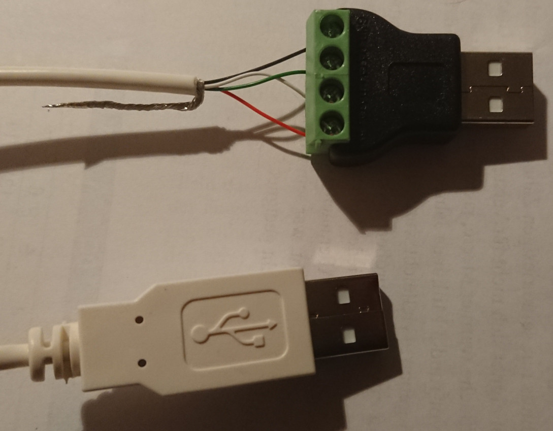
First step is, to program the firmware. There are a couple of preparations needed, e.g. I decided to use method 2 and program via USB. Therefore a non-standard USB A to USB A cable is needed:
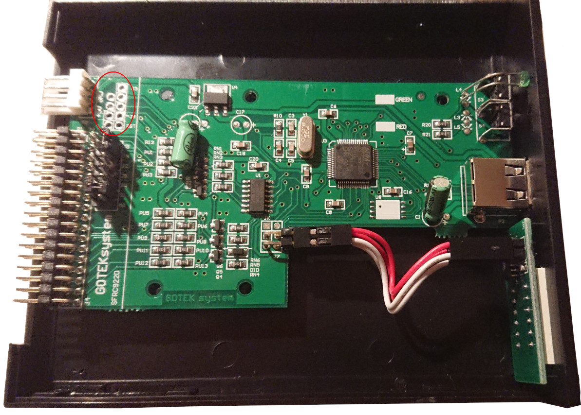
The microcontroller need to be set into the correct boot mode, so that new firmware can be flashed. This is done through some pins. In order to connect these pins, a pin header needs to be soldered first:
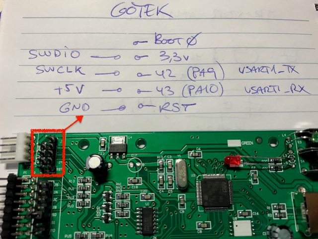
After this pin header is in, we need to connect some of them… the description of the pins is here https://raw.githubusercontent.com/wiki/keirf/FlashFloppy/assets/pheader.jpg:

We need to connect “Boot0” with “3.3V”. This signals the microcontroller to boot into boot-mode, where firmware can be flashed.
We also need to connect “42 (PA9) USART1_TX” with “+5V”. This signals, that we want to use USB for firmware flashing.
This is also explained in the video Flash GOTEK Floppy without Serial Adapter.
Once we have this connection, we need some flashing software: sudo apt install dfu-util.
Then you can list the detected devices:
$ sudo dfu-util --list
dfu-util 0.9

Copyright 2005-2009 Weston Schmidt, Harald Welte and OpenMoko Inc.
Copyright 2010-2016 Tormod Volden and Stefan Schmidt
This program is Free Software and has ABSOLUTELY NO WARRANTY
Please report bugs to http://sourceforge.net/p/dfu-util/tickets/

Found DFU: [0483:df11] ver=2200, devnum=84, cfg=1, intf=0, path="1-2.2", alt=1, name="@Option Bytes  /0x1FFFF800/01*016 e", serial="STM32"
Found DFU: [0483:df11] ver=2200, devnum=84, cfg=1, intf=0, path="1-2.2", alt=0, name="@Internal Flash  /0x08000000/128*002Kg", serial="STM32"
It should display these two devices.
Then it’s time to flash the new firmware. Download the latest release from FlashFloppy.
The zip file contains the file FF_Gotek-v3.27.dfu, which we will need.
If you flash the first time, you need to unlock the microcontroller. The original firmware is read-protected. When we unlock the STM32, the firmware is wiped. So, there is no way back to the original GoTek firmware.
The command to remove the protection and flash the firmware: sudo dfu-util -a 0 -s :unprotect:force -D FF_Gotek-v3.27.dfu
After that, you can update via: sudo dfu-util -a 0 -D FF_Gotek-v3.28.dfu
Wait until dfu-util --list show the device again, then disconnect from USB and remove the jumpers/connections on
the pin header.
Read the instructions on Initial Setup. I want to use the floppy emulator as drive 0, so I need to set the Jumper from S1 to S0.
USB Stick
Now it’s time to prepare a USB stick, that will store the floppy images. The stick must use FAT32 as filesystem.
There can be two files in the root filesystem: FF.CFG which configures flash floppy.
See FF.CFG Configuration File
and the example FF.CFG for default
values and options.
The other file is IMG.CFG which configures floppy image formats.
See IMG.CFG Configuration File
and the example IMG.CFG
As I want to use flash floppy for my alphatronic, I need to configure a single sided, double density, 40 track drive. My file looks like this:
[ssdd40::163840]
cyls = 40
heads = 1
file-layout = sequential
secs = 16
bps = 256
mode = mfm
rpm = 300
Floppy Drive Interface
Now the hardest part: Connecting flash floppy with the real hardware.
It turns out, that the alphatronic doesn’t use a standard 34 pin ibm pc or shugart interface. It has 34 pins though, that’s good. So you can physically connect it.
The original drive is a “BASF 6106”. You can search this and find the manual for the “BASF 6106 Mini Disk Drive”. E.g. you find https://www.abc80.net/archive/luxor/diskdrives/drives/BASF-6106-Mini-Disk-Drive.pdf. There on page “3-3” is Figure 3-3 “Interconnecting diagram”.
For convenience, here’s the pinout of this drive in tabular form:
| Pin | Description | Direction |
|---|---|---|
| 2 | Head Load/ | In |
| 4 | Unused | - |
| 6 | Ready/ | Out |
| 8 | Index/ | Out |
| 10 | Select 1/ | In |
| 12 | Select 2/ | In |
| 14 | Select 3/ | In |
| 16 | Motor On/ | In |
| 18 | Direction In/ | In |
| 20 | Step/ | In |
| 22 | Write Data/ | In |
| 24 | Write Gate/ | In |
| 26 | Track 00/ | Out |
| 28 | Write Protect/ | Out |
| 30 | Read Data/ | Out |
| 32 | Unused | - |
| 34 | In Use/ or Disk Change/ | Out |
As usual, all odd pins (1,3,…) are GND.
The differences with the ibm pinout is this:
- Pin 2 is used for density select and the other direction (to the floppy).
- Pin 6 is not connected, but the alphatronic needs this: With this pin, the floppy drive signals, that it is ready…
- Pin 10 is motor enable A. As we install the flash floppy as drive 0, alphatronic will pull down select 1 and flash floppy will interpret it as “enable motor”. That’s fine.
- Pin 12 is drive select B. Exactly the same like Select 2/.
- Pin 14 is drive select A. Flash floppy will need this, but alphatronic won’t pull this down…
- Pin 16 is motor enable B. Alphatronic will pull this down. But this should be ignored by flash floppy, since the emulated drive is not selected.
- Pin 32 is used for head select.
I found a nice summary of the differences on https://retrocmp.de/fdd/general/floppy-bus.htm with different drives.
So there are two pins, that are a bit more difficult: Pin 6 and 14. But the solution is easy. We can say, flash floppy is always ready. So we connect Pin 6 with GND.
Pin 14 is a bit different. Basically, when alphatronic selects the drive, it pulls down Pin 10. But what we need is Pin 14… so easy fix: Connect Pin 10 and 14.
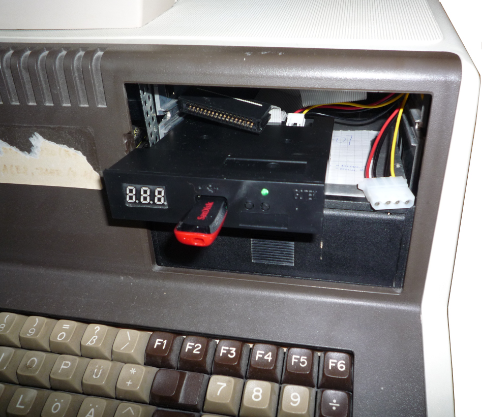
With these two changes, flash floppy works as floppy drive in the old alphatronic. It can boot and it can write to the images on the usb stick.
Here’s a photo of the completed setup:
Comments
No comments yet.Leave a comment
Your email address will not be published. Required fields are marked *. All comments are held for moderation to avoid spam and abuse.